Design a serial adder circuit using Verilog. The circuit should add two 8-bit numbers, A and B.
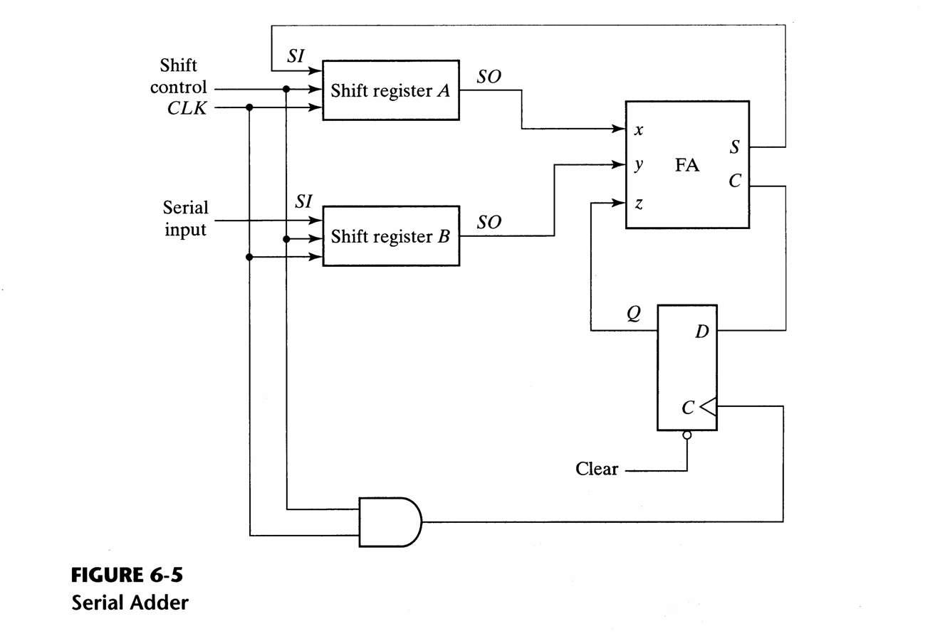
The result should be stored back into the A register. Use the diagram below to guide you.
Hint: Write one module to describe the datapath and a second module to describe the control.
Annotate your simvision trace output to demonstrate that the adder works correctly.
Demonstrate by adding $45 to $10 in your
testbench.