Computer
Imaging: Digital Image Analyis and Processing
Scott
E Umbaugh, The CRC Press, ISBN: 0-84-932919-1.
Errata
File
August 11, 2008
Errors/Changes for the 4th printing of the book:
Ø
Chapter 6, p. 275, the variance (sigma) equations, the
‘1s’ should be ‘i’and ‘j’, respectively:
 It is:
It should be:

Ø
Chapter 10, p. 494, Example 10.2.4, the closing
bracket on the second line of the equation is in the wrong place, it should be
at the end:
It is:
![]()
It should be:
![]()
January 17, 2007
Errors/Changes for 1st, 2nd, and
3rd (Nov 2006) printing of the book:
Ø
Chapter 3, page
72, middle of page, convolution mask for 1st order hold should be:
 Note: the zeros in
the corner of the original should be ¼
Note: the zeros in
the corner of the original should be ¼
Ø
Chapter 3, p. 85, second line of text from the bottom
of the page, change “lines” to “edges”:
It
is:
“…,
corresponding to lines in the vertical,”
It
should be:
“…,
corresponding to edges in the vertical,”
Ø
Chap. 4, p. 140, caption of Figure 4.2.12c:
It is:
“(c)
Roberts result, FOM = 0.853”
It should be:
“(c)
Roberts result, FOM = 0.498”
Ø
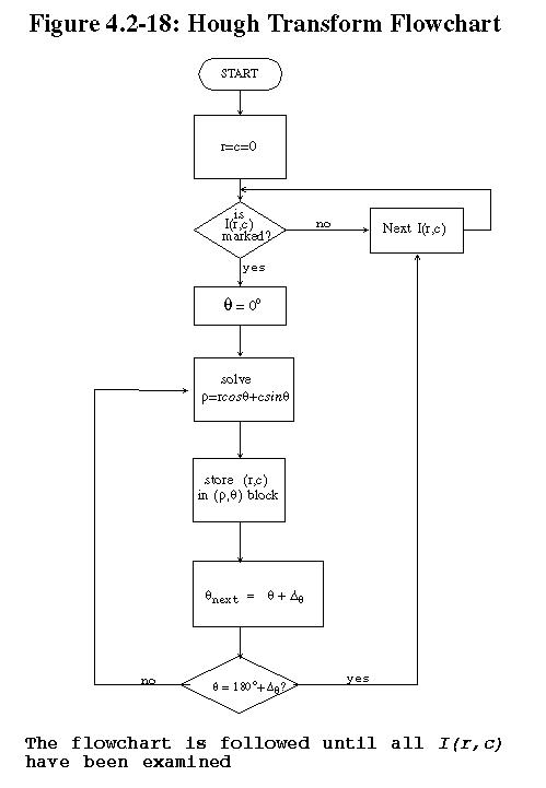
Chapter 4, p. 148, figure 4.2.18. In the flowchart the
“-90” should be “0”, and the “90” should be “180”, as follows:
Ø
Chapter 4, Example 4.3.1, bottom of p. 169, the STRUCTURING
ELEMENT is incorrect:
It
is:

It
should be:

Ø
Chapter 4, Example 4.3.2, p. 171, the IMAGE is
incorrect; 4th row, 4th
column, the ’0’ should be a ‘1’:
It
is:
It
should be:
Ø Chapter 4, Example 4.3.2, p. 171, the RESULT is incorrect; 5th row, 2th column, the ’0’ should be a ‘1’:
It should be:
Ø
Chapter 4, Example 4.3.3, p. 178, middle of the page,
“the resultant image” is incorrect:
It
is:
It
should be:
Ø
Chapter 4, Example 4.3.8, p. 181, middle of the page,
“the resultant image” is incorrect:
 It is:
It should be:
Ø
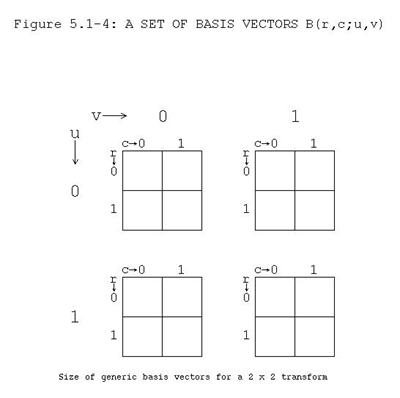
Chap 5, p. 204, Fig. 5.1.4. The layout of the figure
was changed so that all four of the boxes are across the page – this is wrong;
it is critical they are laid out (two-dimensionally) as follows:
Ø
Chapter 5, p. 207, Figure 5.2.1 caption, (b)-(e):
It is:
“(b)The fundamental. (c) The first
harmonic. (d) The second harmonic. (e) Approximation to the sum of the
fundamental and the first three harmonics.”
It should be:
“(b)The fundamental, or first harmonic.
(c) The second harmonic. (d) The third harmonic. (e) Approximation to the sum
of the first three harmonics.”
Ø
Chapter 5, p. 209, the equation in the middle of the
page, after “The inverse DFT is given by:”, the I(r,c) should be I(c),
and the 1/N should not be there, as follows:
It is:
![]()
It should be:
![]()
Ø
Chapter 5, p. 209, the lower part of the page, change
the “R(v)” to “Re(v)”and “I(v)” to “Im(v)” in both the equations and text. This
is needed in a total of five “R(v)” and “I(v)” pairs.
It is:
“…the one-dimensional DFT equation can
be written as:
![]()
In this case, F(v) is also complex, with the real part corresponding to the
cosine terms, and the imaginary part corresponding to the sine terms. If we
represent a complex spectral component by F(v) = R(v) + jI(v), where R(v)
is the real part and I(v) is the imaginary part, then we can define the
magnitude and phase of a complex spectral component as:
![]()
and
![]()
It should be:
“…the one-dimensional DFT equation can
be written as:
![]()
In this case, F(v) is also complex, with the real part corresponding to the
cosine terms, and the imaginary part corresponding to the sine terms. If we
represent a complex spectral component by F(v) = Re(v) + jIm(v), where Re(v) is the real part and Im(v) is the
imaginary part, then we can define the magnitude and phase of a complex
spectral component as:
![]()
and
![]()
“
Ø
Chapter 5, p. 210, Figure 5.2.4, change the “R(v)” to
“Re(v)”and “I(v)” to “Im(v)” in both the equations and text. Below is the
corrected figure:
Figure 5.2.4 Complex Numbers. a) A
complex number shown as a vector and expressed in rectangular form, in terms of the real, Re, and
imaginary components, Im, b) a complex number expressed in exponential form in
terms of magnitude, M, and angle, θ. Note that θ is measured
from the real axis counterclockwise.
a) 
b) 
Ø
Chapter 5, p. 211, Example 5.2.2, the third equation
down has an extra “2” in it:
It
is as follows:
![]()
It
should be:
![]()
Ø
Chapter 5, p. 212, first equation at top of page:
It
is:
![]()
It
should be:
![]()
Ø
Chapter 5, p. 213, top to middle part of the page,
change the “R(v)” to “Re(v)”and
“I(v)” to “Im(v)” in both
the equations and text; there are four “R(v)” and “I(v)” pairs.
It is:
“If we represent a complex spectral
component by F(u,v) = R(u,v) + jI(u,v), where R(u,v) is the real
part and I(u,v) is the imaginary part, then we can define the magnitude
and phase of a complex spectral component as:
![]()
And
![]() “
“
It should be:
“If we represent a complex spectral
component by F(u,v) = Re(u,v) + jIm(u,v), where Re(u,v) is the
real part and Im(u,v) is the
imaginary part, then we can define the magnitude and phase of a complex
spectral component as:
![]()
and
![]() ”
”
Ø
Chapter 5, Section 5.2.2, page 214, second equation on
the page. The first “vc” should be “
It
is:
![]()
It
should be:
![]()
Ø
Chapter 5, p. 215 under 5.2.3.4 Modulation. The
equations are missing the 1/N term in the exponent, they should be:

Ø
Chapter 5, page 217, bottom of page, last part of
equation is “v = N”, it should be “v + N”.
It is:
![]()
It should
be:
![]()
Ø
Chapter 5, page 247, PERIODICITY equation, last part
of equation is “v = N”, it should be “v + N”.
It is:
![]()
It should
be:
![]()
Ø
Chap 5, p. 218, Section 5.2.4, first sentence, it says:
“The Fourier spectrum consists of
complex floating point numbers, which are stored in CVIPtools as a two band
image – one band for the real plane data, and one band for the imaginary plane
data.”
It should be:
“The Fourier spectrum consists of complex
floating point numbers, which are stored in CVIPtools as in a single band image
with a data format of complex. “
Ø
Chapter 5, p. 227, Example 5.4.3, the second line, the
figure number is wrong.
It is as follows: “image in Figure
2.5.10…”,
It should be: “image in Figure 5.4.3…”
Ø
Chapter 5. p. 231, (RGB’s missing) equation after “3.
Perform the linear transform on the RGB data…”
It
is as follows:

It
should be:

Ø
Chapter 5, p. 236, Figure 5.7.6, the images in (d) and
(e) need to be swapped.
Ø
Chapter 5, p. 236, Figure 5.7.6, the caption is wrong,
it should be as follows:
“Figure 5.7.6 Highpass filter functions.
a) 1-D ideal highpass filter. b) 1-D nonideal highpass filter. c) 2-D ideal
highpass filter for Fourier symmetry, shown as an image. d) 2-D nonideal
highpass filter for Fourier symmetry. e)
2-D ideal highpass filter for cosine and Walsh-Hadamard symmetry. f) 2-D
nonideal highpass filter for cosine and Walsh-Hadamard symmetry. Note: for the
filters shown as images, white =1, black = 0, and gray values in between
represent values between 0 and 1, corresponding to the transition band in
nonideal filters.”
Ø
Chapter 5, p. 237, Figure 5.7.7, the caption is wrong, it should be as follows:
“Figure 5.7.7 High frequency emphasis
filter functions. a) 1-D ideal high frequency emphasis filter. b) 1-D nonideal
high frequency emphasis filter. c) 2-D ideal high frequency emphasis filter for
Fourier symmetry, shown as an image. d) 2-D nonideal high frequency emphasis
filter for Fourier symmetry. e) 2-D
ideal high frequency emphasis filter for cosine and Walsh-Hadamard symmetry. f)
2-D nonideal high frequency emphasis filter for cosine and Walsh-Hadamard
symmetry.
Ø
Chapter 5, p. 239, Section 5.8 Wavelet Transform, the
second paragraph, third sentence (swap the last “vertical” and “horizontal”).
It is as follows:
“The results consist of one image that
has been highpass filtered in both the horizontal and vertical directions, one
that has been highpass filtered in the vertical and lowpassed in the
horizontal, one that has been highpassed in the vertical and lowpassed in the
horizontal, and one that has been lowpass filtered in both directions. “
It should be:
“The results consist of one image that
has been highpass filtered in both the horizontal and vertical directions, one
that has been highpass filtered in the vertical and lowpassed in the
horizontal, one that has been highpassed in the horizontal and lowpassed in the
vertical, and one that has been lowpass filtered in both directions. “
Ø
Chapter 5, p. 241, Example 5.8.2. The “origin” and its
corresponding arrow in the equations are pointing at the wrong coefficient.
They should be as follows (need to be moved to the right):


Ø
Chapter 5, p. 246, under One-dimensional DFT, second
line of the FORWARD equation, change the “R(v)” to “Re(v)”and “I(v)” to “Im(v)”.
It is:
![]()
It should be:
![]()
Ø
Chapter 5, p. 246, under One-dimensional DFT, INVERSE
equation, change “I(r,c)” to “I(c)” and remove the “1/N” term:
It is:
![]()
It should be:
![]()
Ø
Chapter 5, p. 246, under “One-dimensional DFT” change
the “R(v)” to “Re(v)”and
“I(v)” to “Im(v)” in the
MAGNITUDE and PHASE equations.
It is:
![]()
![]()
It should be:
![]()
![]()
Ø
Chapter 5, p. 247, middle of page, under MODULATION.
The equations are missing the 1/N term in the exponent, they should be:
Ø
Chapter 5, p. 251, Wavelet Transform, 5th
bullet (swap the last “horizontal” and “vertical”):
It
is as follows:
“The wavelet results consist of one
subsampled image that has been highpass filtered in both the horizontal and
vertical directions, one that has been highpass filtered in the vertical and
lowpassed in the horizontal, one that has been highpassed in the vertical and lowpassed in the horizontal, and one that has been
lowpass filtered in both directions. “
It
should be:
“The wavelet results consist of one
subsampled image that has been highpass filtered in both the horizontal and
vertical directions, one that has been highpass filtered in the vertical and
lowpassed in the horizontal, one that has been highpassed in the horizontal and lowpassed in the vertical, and one that has been
lowpass filtered in both directions. “
Ø
Chapter 6, p. 276, bottom of page, equation for Laws
wave, W5 (the last ‘-1’
should be a ‘1’):
It is:
“W5 = (-1,
2, 0, -2, -1)”
It should be:
“W5 = (-1,
2, 0, -2, 1)”
Ø
Chapter 6, p. 295, middle of page, equation for Laws
wave, W5 (the last ‘-1’
should be a ‘1’):
It is:
“W5 = (-1,
2, 0, -2, -1)”
It should be:
“W5 = (-1,
2, 0, -2, 1)”
Ø
Chapter 8, Section 8.2.3, p. 370, equations for
Log-ACE , definition of MAX.
It
is:
“…MAX
is maximum gray value (e.g. 255)”
It
should be:
“…MAX
is number of gray values (e.g. 256)”
Ø
Chapter 8, Section 8.2.3, p. 370, equations for
Exp-ACE , definition of MAX.
It
is:
“MAX
= maximum gray value (e.g. 255)”
It
should be:
“MAX
= number of gray values (e.g. 256)”
Ø
Chapter 8, p. 391, 8.5 Key Points, GRAY SCALE
MODIFICATION, bullet one:
It
is as follows: “Gray scale modification is also called gray level scaling or
gray level modification”
It
should be: “Gray scale modification is also called gray level scaling or gray
level transformation”
Ø
Chapter 9, p. 427, equations on bottom that have
I(r,c) should be d(r,c):
It is: 
It should be: 
Ø
Chapter 9, p. 429-430 & 465, the subscripts min and max need swapped, in two places.
It is:

It
should be:

Ø
Chap. 9, p. 454, Example 9.6.1, the last line:
It is:
“Now,
we let I(2,3) = d(39,27)”
It
should be:
“Now,
we let I(2,3) = d(39,17)”
Ø
Chapter 10, p. 494, Example 10.2.4, the closing
bracket on the second line of the equation is in the wrong place, it should be
at the end:
It is:
![]()
It should be:
![]()
Ø Chap. 10, p. 515, middle of page, the first I-tilde should be I-hat
It is as follows:
“This error signal is then
quantized, such that:
![]() ”
”
It should be:
“This error signal is then
quantized, such that:
![]() ”
”
Ø Chap. 10, p. 533, Fig.
10.3.24. The images in (d) and (e) need to be swapped (note: it is correct in
the color plate).
Ø
Chapter 11, p. 562, number 9, the “print_CVIP” line of
code has an extra “rdquo;” that needs to be removed.
It is:
print_CVIP("test
new function, return value is %d\n",rdquo; test_function(1));
It should be:
print_CVIP("test
new function, return value is %d\n",test_function(1));
Ø Chap 12., p. 596, under the
morpho function, fifth line (change to “a+b”):
It
is as follows:
“boolFUNC>
‑ integer number for the Boolean function (1‑6): 1: 0, 2: !a, 3: ab,
4: a plus;b,
It should be:
“boolFUNC> ‑
integer number for the Boolean function (1‑6): 1: 0, 2: !a, 3: ab,
4: a+b,”
Ø
In the index, p. 648, under “Data”, add the following
entry:
“structure, 566, 569-573”
Ø
In the index, p. 652, under “Image”, add the
following:
“structure,
570”
Ø
In the index, p. 654, under “Matrix”, add the
following:
“structure,
569”
Ø In the index
on page 656, the entry for Reflectance function should also have page 382.
It is:
“Reflectance
function, 20, 21, 58”
It
should be:
“Reflectance
function, 20, 21, 58, 382”