Outside Slide Needle Float Pilot Jet Needle Jet Main Jet
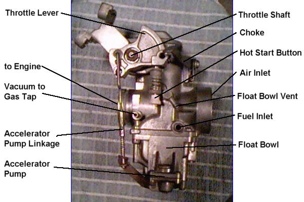
Starting at the top and left side of the carburetor, we have the throttle shaft and lever, this is where the push-pull throttle cable hooks up to the carburetor. The accelerator pump linkage, hot start button and an adjusting screw for maximun slide travel work off of the throttle lever. The Hot Start Button is used to hold open the throttle just enough to make hot starts easier.
Next we visit the Choke, which Mikuni likes to call an enrichener starting system, but still stamp "Choke" on the lever, it is not a choke because it doesn't block off the throat of the carburetor to limit air intake and thus enrichen the mixture for starting. The starting system works by opening a passage that allow more fuel to pass through a different set of jets making the mixture richer. The starting system (choke) only works if the throttle is kept closed, if you give the carburetor any throttle with the starting system on it won't work.
Also on the the left side of the carburetor is the vacuum to operate the gas tap, the fuel inlet, where the gas line attaches, and the float bowl vent. The vent allows air to escape as the fuel come in. At the bottom of the carburetor is the float bowl or chamber and the accelerator pump.
Now on to the right side. On this side we have the enricher valve, this is vacuum operated valve that enriches the mixture when the throttle is close quickly during high speed operation and is used to prevent abnormal combustion caused by a lean mixture. The float bowl drain screw and overflow are also located on the right side of the carburetor.
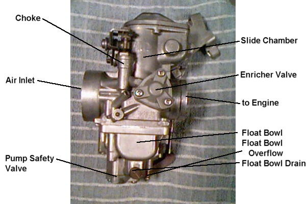
At the bottom of the float bowl is the pump safety valve, this is another vacuum operated valve that disables the accelerator pump when the engine is not running, no vacuum, no accelerator pump.
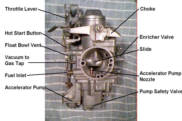
I have included a view from the air cleaner so you can better see where some of these things are located. You can also see the accelerator pump nozzle in this view, this is where the fuel sprayed when the throttle is opened.
Now, let's take a look at the inside of this thing, starting at the top, and see what makes it tick. To remove the slide, first pry the accelerator pump linkage out of the throttle lever then remove the two philips secrews from the cap on top of the carburetor. You will see a bolt through the throttle shaft, secured with a taplock, pry the tab back and remove the bolt with a 7mm wrench. After removing the bolt, slide the throttle shaft out the left side of the carburetor, make note of how the return spring attaches to the throttle lever and the carburetor body. Set the shaft and lever assembly aside and remove the slide.
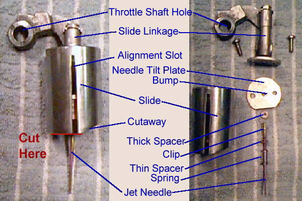
The slide should look like the picture on the left. The slide linkage lifts and lower the slide as the throttle is opened and closed. The job of the slide is to regulate the amount of air entering the engine. The alignment slot and corresponding pin in the carburetor body is to keep the slide from rotating, this keeps the cutaway toward the inlet side (air cleaner side) of the carburetor.
Next, remove the two philips screws that hold the linkage to the slide, then remove the jet needle, most commonly called the needle, and related spring, spacers and clip. Now you should have a bare slide and be ready to perform the tricky part of the Minton Mods. The cutaway is the diagonal cut on the bottom of slide. When performing the Minton Mods remove .050" from the bottom of the slide in the area indicated by the red line, DO NOT remove any material from the cutaway itself. By reducing the size of the cutaway, the amount of air being drawn into the carburetor is less, resulting in a richer mixture. This corrects the lean condition off of idle to 1/4 throttle. Joe Minton says "You can do this with a sharp file and, if you are reasonably careful, can save the price of an aftermarket carb" and Bill Vonderhey offers this advice "File .050" off the bottom of the slide, making sure that the bottom edges are square with the slide and that all sharp edges are slightly bevelled and smooth.". So, take a deep breath and GOOD LUCK!
The next adjustment is the needle (jet needle). The needle, with the needle jet, controls the amount of fuel added to the mixture from 1/4 to 3/4 throttle. The adjustment is done by removing the "E" clip from the needle and moving it either up or down one of the five grooves. Here is where the terminology get tricky, when you move the clip toward the top, it lowers the needle. The needle gets fatter as it goes up, so, as you lower the needle you restrict the amount of fuel at any given time, and a leaner mixture results. Reverse the process to richen the mixture.
One other thing to note before we move on is the needle tilt plate. The bump on the tilt plate is located on the botton of the plate and when properly installed presses on the large spacer on the top of the needle. This tilts the needle away from the cutaway, if you look close you can see this in the picture on the left. When you put the slide back in the carburetor body align the slot on the slide with the pin on the body and as you lower the slide put your finger in the outlet of the carburetor and push the needle toward the air cleaner side so it will mate with the needle jet nozzle (hole in the bottom of the carburetor throat).
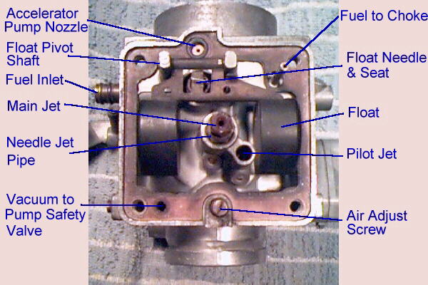
OK, let's move on to the bottom of the carburetor. Turn the carburetor upside down and remove the four philips screws that hold the float bowl onto the carburetor body. You should see what is in the picture above. The accelerator pump nozzle is the passage that takes fuel from the accelerator pump on the bottom of the float bowl to the nozzle in the throat of the carburetor. There is also a pipe that takes fuel from the bowl to the choke, excuse me, enrichner starting system.
Now it's time to look at the float, as you can see, the float assembly pivot on a shaft. As the fuel rushes into the bowl the float starts to rise and pushes the float needle into the seat. When to fuel level reaches the proper height the needle and seat shut off the flow of fuel. Pretty simple don't you think? To adjust the float level, turn the carburetor upside down so the weight of the floats is on the needle and seat and measure the distance from the gasket mating surface (without gasket) of the carburetor body to the bottom of the float (remember the carburetor is upside down, so the bottom is the upper most portion of the float) it should measure 23.5 mm plus or minus 1 mm.
See that black spot at the end of the line that says pilot jet, that's were the pilot jet lives. Take a small common (straight blade) screwdriver and stick it down in that black hole, trust me, it's in there and unscrew the jet. The pilot jet meters fuel to the engine all the time the engine is running and has less effect on mixture as the throttle opening increases, it's an cumulative thing. Since the pilot jet effects the entire range it should be adjusted first. The air adjust screw is a fine tune for the pilot jet by adding air to the mixture to get it just right. The pilot jet is adjusted by replacing it with a different size, larger number gives richer mixture. They are standard Mikuni pilot jets and are available at your local motorcycle shop.
The last stop on the tour is the needle jet and the main jet. The main jet regulates the fuel flow at 3/4 to wide open throttle (WTO). The main jet is also a standard large (long) hex main jet, there are other styles, but just ask for the large hex, the parts guy will know what you mean. Here again, the larger the number the richer the mixture. The needle jet on the VM34SS is not standard Mikuni fare, it's a two piece thing with part stuck up inside the carburetor. The assembly is removed by unscrewing the needle jet pipe from the carburetor body, the main jet is screwed into the needle jet pipe. The needle jet pipe does not adjust the mixture, that is the function of the main nozzle. The main nozzle is pressed into the carburetor body by the needle jet pipe, in the standard Mikuni VM carburetor the nozzle and the pipe are one piece and are installed through the slide chamber and held in place by the main jet. This is not the case with the VM34SS, to remove the main nozzle you will need a long brass or aluminium drift about a 1/4" in diameter to insert into the slide chamber and tap the nozzle out through the bottom of the carburetor. The needle jet (nozzle and pipe) work with the jet needle as described earlier. The Sudco catalog list two different sizes of main nozzles, a P-8 (003-531) and a P-6 (003-530) the P-8 is richer. The Vonderhey article mentions a next-larger-larger size main nozzle, but I haven't found a part number for it yet.
Well, this concludes our tour of the Mikuni VM34SS carburetor as supplied on the 1978 and 1979 Yamaha SR500 single-cylinder four-stroke motorcycle. I hope you have enjoy the tour and find some usefull information in here somewhere. Please watch your step as you exit this page and feel free to visit again, if needed.
If you would like more information on modifing the Mikuni VM34SS, just surf over to SR500 Carb Modification page and check it out.
Any questions, comments or corrections? E-mail me at ron_sutton@yahoo.com