System Description:
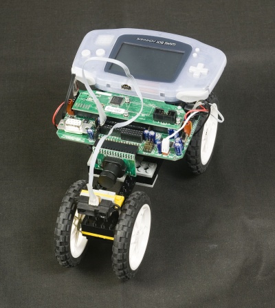
The system is composed of a microprocessor on an XBC board, a car driven by two DC motors (controlled by PWM signals), and a laser range finder measuring the distance to an object in front of the car (a wall in our case). Control logic for the system is written in Interactive C (IC).The output from the range finder is measured using the IC code:
y=analog12(0);
y will be a 12-bit integer measured from analog port 0.
The input is sent to the motors using the code:
motor(0,u);
motor(2,u);
where the motors are connected to ports 0 and 2 and u is an integer between -100 and 100 specifying the PWM duty cycle.
Phase 1:
Objectives:
- Develop a transfer function model of the car, where y (the range finder distance) is the output and u (the motor PWM duty cycle) is the input.
- Design a proportional controller for the system and implement it in IC.
- Accurately predict the step response of the system while under closed-loop control of your proportional controller.
Required Steps:
- System identification data will be collected in class. Bring suggestions for inputs we should try.
- Analyze the system ID data and develop a transfer function model (y/u).
- Design a proportional controller using the Matlab® commands feedback and step (or equivalent Python® commands).
- Implement your controller in IC.
- Gather experimental data for the step response of the car with your proportional controller.
- Compare predicted and actual step response results.
Note:
You will be required to turn in your predicted response before you run the experiment.Optional Step:
As an optional step, you may design your controller using Bode plots. This would be a good learning experience, may be faster than iterating through the feedback and step commands, and will give you a head start on Phase 2.Phase 2:
Develop a more advanced controller for improved performance.- Proportional control is not very sophisticated and may not lead to great performance.
- Identify areas where the performance of your system could be improved.
- Design and implement a control that improves the system response.
Phase 3: System Improvements with PSoC's
There are several problems with the existing system:- The range finder is noisy.
- The XBC micro controller with IC does not do hard real-time control and is not very fast for computations.
- The PWM control implemented by the XBC does not have very fine control and uses a lot of system overhead by doing additional things (like trying to track the motor position through back EMF sensing and integration).
- Lowpass filtering the range finder signal
- Implementing a better PWM controller with finer control
- Implementing a hard real-time controller