|
|
Home->Projects |
 |
From 1999 to 2002, I worked as a primary or associate Geotechnical/Structural Engineer at the Shanghai Tunnel Engineering and Rail Transit Design Consultant. My primary responsiblity includes:
- Designed infrastructures including dams, tunnels, subway stations, light railway systems, and other type of excavation works in challenging metropolitan environment.
- Served as leading 2D/3D finite element analysis engineer.
- Developed numerous engineering drawings with AutoCAD.
- Developed finite element computation and post-processing software.
- Cooperated with construction contractors for engineering support.
- Conducted research on efficient bracing systems for super deep excavation and finite element analysis of complex underground structures.
Selected Infrastructure Projects
|
 |
Shanghai Rail Transit Pearl Line: Lancun Subway Station (2000-2001)
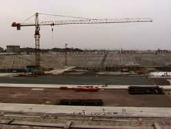
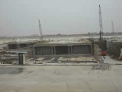
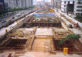
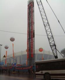
Lancun Subway Station is an interchange station between a subway system and an elevated light rail transit system. Part of the station is buried underneath the soil for the reception of Tunnel Boring Machine(TBM) and part of the station is planed to be above ground in order to integrate the elevated light rail transit system. The uneven distribution of load in terms of magnitude and directions has the high possibility to induce differential settlement. And for the retaining wall, SMW(Soil Mixing Wall) imbedded with steel sheet piles had never been used in Shanghai’s subway construction before this application. The following pictures show the construction site and the Tunnel Boring Machine reception shaft under construction
 |
|
The Construction Site |
Tunnel Boring Machine Reception Shaft |
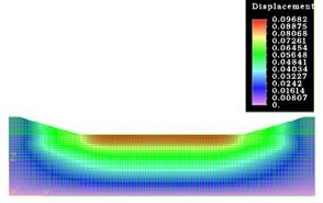
The interaction between the subway facility and the elevated rail system is quite complicated. First, because the elevated rail system will be constructed two years after the completion of the subway station, the shallow water table condition caused the subway station unable to resist buoyancy force. Second, after the construction of elevated rail system, the huge loading from the train will induce excessive settlement of the subway station. Finally, the distribution of train loading and soil burden is also not even due to the different spans of elevated rail bridges and nonuniform subway structure form. Uneven settlement of the subway station caused by these factors cannot be neglected, as shown in Fig 6. After conducting detailed finite element analysis, I proposed to adopt pile footing as a solution to this problem. According to my proposal, the pile footing has different functions in different phases: it will resist the buoyancy force before the construction of the elevated light rail and carry the huge uneven train loading after the construction of the elevated rail system.
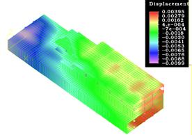
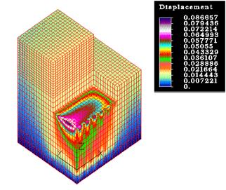
In designing the TBM reception shaft, the shaft under various loading conditions was analyzed by conducting 3-dimensional finite element simulation, as shown in Fig. 7. The simulation results were used to determine the optimum sequences of excavation, installation and uninstallation of bracing system, the thickness of SMW wall and internal walls.

3D Finite Model for the Interchange Area |
The Displacement |
3D Finite Model for the TBM Reception Shaft |
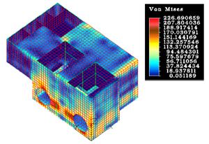
The Stress-state of the Shaft |
For the SMW method, considering little experience available for its performance, we set up a real-time field system monitoring the deformation of adjacent surface and buildings, the stress condition of embedded steel sheet piles, the deformation of the retaining structure, the force of bracing system, the earth pressure on the retaining structure. By analyzing the displacement data acquired from this system, I concluded that SMW as a novel retaining structure was effective in keeping displacement acceptable if the excavation depth was less than 16 m. Furthermore, after the steel sheet pile was pulled from the SMW, the cost of SMW method was only 60% percent of other prevail retaining structures like concrete diaphragm wall.
|
|
Shanghai Rail Transit Pearl Line: Shanghai Gymnasium Subway Station (2000-2001)
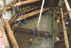
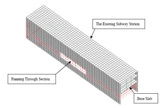
Shanghai Gymnasium Subway Station is the most difficult subway construction project in Shanghai. As shown in Fig. 8, the planed station need to run through the retaining wall of an existing subway station without disrupting the operation of in-service subway system. In the traverse area, the excavation depth exceeded 22m. And along the driving route of Tunnel Boring Machine, the distance between the tunnel and the adjacent high-rising buildings is only 1.5m.
 |
Illustration of Surrounding Construction Environment and Construction Method |
In this project, the situation around the intersection part was extremely complicated. On the left side of the existing subway station, an appropriate running through method and an optimum excavation sequence need to be selected to minimize the disturbance to the running train. On the right side of the existing subway station, a cost and risk evaluation need to conducted to compare the two construction plans: one was to build a TBM reception shaft to take the TBM out for reuse. The other was to leave the shell of TBM underground, so no reception shaft was needed.
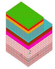
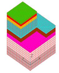
In order to simulate the various conditions discussed above, I developed several 3-D finite element models to analyze the performance of the selected construction method. Fig.9 shows the model for simulating excavation at the left side of the existing station. The analysis involved modeling of the ground, the existed station and the planed station. The incremental stage-by-stage analysis is employed to simulate the excavation process. And in order to decrease the node number with little influence on computing precision, the excavation area and the existed
station is calculated symmetrically. The different colors show the distribution of the geological layers Fig. 11 shows the accumulated rebound during excavation. In these figures, the meshes for the existed station and the shoring system of the foundation pit were hidden.
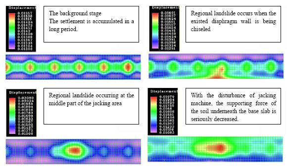
Fig. 12 shows the model for simulating a specified running through method in terms of jacking drive. And Fig. 13 shows the settlement of the base slab under possible situations during the jacking driving process, this analysis involved modeling of the existed station and jacking machine. The soil underneath the base slab is simulated by a series of boundary elements. By alternating the stiffness of some boundary elements, I can simulate the different regional soil collapse during construction.
 |
 |
 |
FEA Model Before Excavation |
FEA Model After Excavation Completed |
Distribution of Heave During Excavation |
|
Settlement of the Base Slab of the Existing Station during Different Stages (Units: m) |
The simulation results revealed a number of very important issues: First, on the left side of the existing subway station, the excavation of the planed subway station would cause significant soil heave, the existing station will suffered from excess torsion effect. Second, on the left side of the existing subway station, not a single running through method can provide acceptable settlement control. However, jacking a steel hollow box underneath the existing subway station can provide minimum settlement. And if the method is combined with freezing soil method, the required control of settlement can be achieved. Third, on the right side of the existing subway station, constructing a reception shaft would be very dangerous and high cost compared with leaving the shell of TBM underground. All these important conclusions from my finite element analysis have been accepted, the proposed methods also have been used in the real construction. Fig. shows the installation of retaining wall at the left side of the existing subway station. Fig. 14 shows the utilization of freezing soil method.
 |
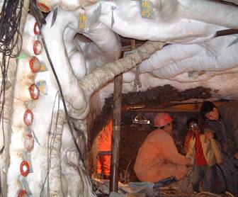 |
Installation of Reinforcement for 150 Feet High Concrete Retaining Wall |
Adoption of Soil Freezing Methodl at Running Through Section |
At the right side of the existing station, the selected TBM is EPBS. In shield driving, the separate components of the excavation support (borefront, shield jackets, transition zone, shield/tunnel segments) cause changes in the stress situation in the subsoil by which short-term and long-term settlements will develop. And the settlement trough caused by the boring process moves forward together with the TBM as a wave and has a decisive influence on the deformation behavior of adjacent buildings. Because there are lots of buildings adjacent to the driving path, an Interactive Boring Control System (IBCS) was introduced to minimize the impact to the surrounding facilities. It consists of three parts: virtual tunneling with numerical 3D-model; monitoring actual effects on buildings, ground and in TBM; determination of optimized boring process parameters for next boring section.
|
|
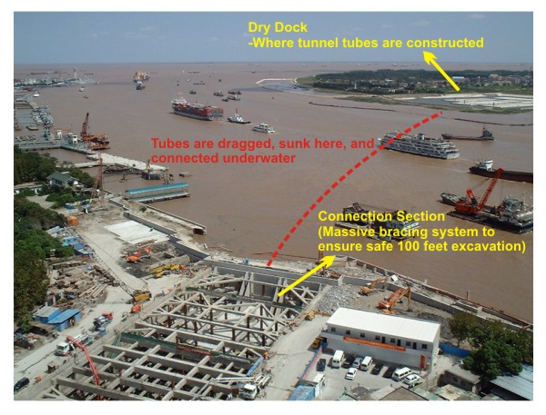
Shanghai Outer Ring Immersed Tunnel (1999-2001)
Shanghai Outer Ring Immersed Tunnel is the largest immersed tunnel in Asia, second in the world. In the project, I was responsible for analyzing the stability of dry dock during excavation and the settlement of tunnel elements during construction in the dry dock. The following figure shows the dry dock, sinking site and the connection section.
|
Overview of Immersed Tunnel Construction |
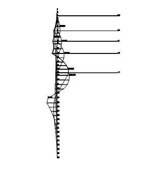
For excavation analysis, a two-dimensional finite element model is adopted. The analysis consisted of four steps, as described below.
- Step 1. The initial ground condition is imposed. Gravitational forces are applied to the entire mesh.
- Step 2. The excavation process consists of eliminating the excavated element from the stiffness matrix and applying representative traction forces at the excavation boundary through the global equilibrium of forces.
- Step 3. Constructing a grouting foundation. Grout pressure is applied to the soil at the bottom of pit.
- Step 4. Constructing submerged tubes on the foundation incrementally. The weight pressure caused by tubes is applied on foundation incrementally.
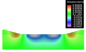
The following figures show the analysis results for step 2 and step 4.
|
|
Simulation and Excavation of Dry Dock (units in meter) |
|
|
Simulation of Construction of Tube Elements (units in meter) |
According to my calculation, the weak interlayer induced most of the settlement during constructing tunnel elements. My opinion based on the finite element analysis was to use deep mixing method as soil improvement measure. Moreover, I also found the distance between adjacent tunnel elements has significant influence on the magnitude of differential settlement. Keeping sufficient distance could minimize the influence of adjacent settlement basins. |
|
Design & Research of the Post-Process Program for ALGOR FEAS (2000- 2001)
Award: Shanghai Science and Technology Award (2001)
Underground transportation system is a possible solution to the dense traffic condition in metropolis. However, the construction of underground infrastructures is usually very difficult because of complicated construction environment and strict requirement of environment protection. The behavior of soil structure interaction in certain cases are very important for predicting movement of surrounding facilities. So there is a big need for powerful numerical simulation programs to model these behaviors. Algor FEA is a general purpose commercial finite element package which is widely used by civil engineer in designing. This software certainly can be used to conduct analysis, however, several shortcomings should be overcome before it can be reliably used in real projects.
First, the results from Algor are not convenient for civil engineer to interpret and use for calculation the distribution of reinforcement. Second, for some large 3-dimensional models, the checking procedure in the software serves little purpose. A systematic and synchronic modeling and checking procedure should be developed with the aim of balance between minimum error and minimum cost. Finally, for a series of construction sequences, especially continuous excavation, Algor does have the ability to analyze each case, but for the combination of critical cases, it is disappointing. A coordinate program should be developed to help Algor synthesis different cases.
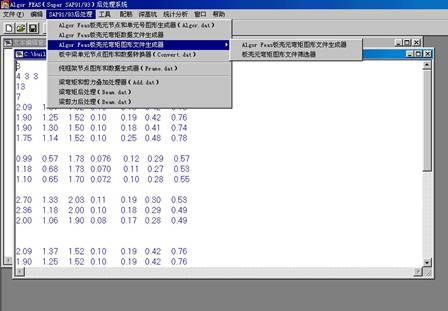
This research project focus on the solution to these problems. As a result, a post-process program was developed by using C++ with OOP technique, as shown as follows.
|
User Interface of the Program |
As a key member of the research group, I was responsible for several tasks. One is to use Algor FEA extensively to simulate lots of common construction cases, and compare the results from Algor with the theoretical solution if it is available. And I need to gather the feedback about the feasibility of Algor from myself and other engineers in our institute. Another one is to develop the source code for the generator of dxf files which include geometric information about the mesh and the moment of plates, the moment and shear force of the beams. About the moment of plates, in order to avoid unreadable results from high density mesh, a smart selection algorithm was developed to show key moment according to the advice from very experienced engineers. Except that, all these results can easily be combined according to the requested construction sequences. Optimal reinforcement calculation was also suggested below the plot of plate moment. Finally, I was asked to prepare the manual for the systematic model approach and the operation of the software. I also gave a seminar about the program to demonstrate the whole
systematic modeling and checking procedure.
|
|
The output moment for plate |
The output moment for beam |
|
|
Excavation Sequence Calculation |
Automated Overlay of Different Excavation Steps |
|
 |
|
|